Isolated SerialExpress signals
![]()
With copper-based SerialExpress cables, high-speed signals are sent over differential twisted pair 150 ohm conductors between AC-coupled transmitters and receivers, illustrated below. The AC coupling simplifies the receiver/transmitter designs, allowing the bias points of each can be set independently.

Signal integrity is also improved, allowing data to be clocked at higher rates over longer distances. The capacitors have the behavior of open circuits, for low-frequency noise, effectively breaking the ground loop that would otherwise form through the system's green-wire grounds.
![]()
In telecommunication communication applications, all cable signals are required to be isolated from ground, which mandates capacitive coupling at the transmitter as well as receiver, as illustrated below. This isn't just a good design practice, in Europe its the law!

Note that consumer and telecom equipment are interoperable, in
that consumer equipment can be directly attached to telecom
equipment. However, due to the ground-coupling of cable through the
consumer device, such mixed systems cannot be used in telecom
applications. ![]()
Either capacitive or transformer isolation can be used: capacitive isolation is less expensive and transformer isolation is less sensitive to common mode noise. In both cases, termination resistors rt are used to match the line impedance; resistors ra and rb are used to set the receiver circuits DC-bias point.

Note that consumer and telecom equipment are interoperable, in
that consumer equipment can be directly attached to telecom
equipment. However, due to the ground-coupling of cable through the
consumer device, such systems cannot be used in telecom applications.
![]()
Cable shields isolate the signal wires from external noise sources and reduce EMI emissions from the signals being transmitted. Although a common shielding technique is to attach the shield to the equipment chassis, this would have several problems, because significant voltages differences may exist between chassis grounds:
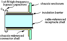
Consistent with established Ethernet precedence, our cables are fully isolated. The shield isolation is performed at the connector receptable, as schematically illustrated below:

![]()
The SerialExpress connectors have other signals, which are isolated as follows.